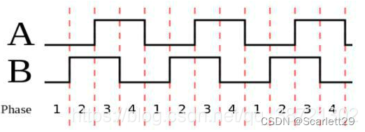
旋转编码器产生A B两个脉冲信号,通过STM32配置定时器检测编码器的速度及正反转。通过软件的方法实现四倍频,A B脉冲相差90度,A脉冲占据4个单位时间,B脉冲占据4个单位时间,当定时器同时检测A B脉冲,会提高分辨率,周期变为2个单位时间。
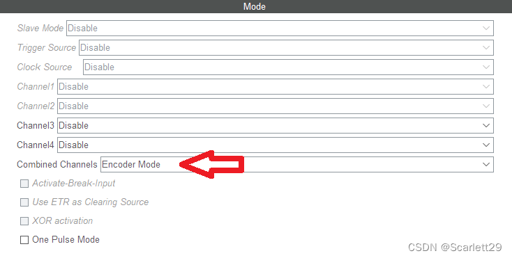
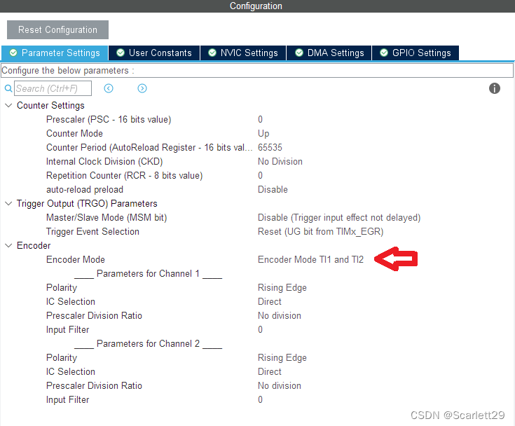
配置HAL的TIM模式及编码器模式。
敲代码
编写int getTimEncoder(void)接收定时器的数字。在一个时间段内,检测编码器脉冲数后,需定时器要重新置零。
重点:正反转需要强制类型转换(short)(__HAL_TIM_GET_COUNTER(&htim1)),变成一个有符号类型。如反转是会输出65500多的数字,强制类型转换后变成一个负数。
int getTimEncoder(void)
{
  int iTimerEncoder = 0;
  iTimerEncoder = (short)(__HAL_TIM_GET_COUNTER(&htim1));  //强制类型转换为short,分辨正反转
  __HAL_TIM_SET_COUNTER(&htim1, 0);                        //重新TIM计数器设置为0,避免计数器溢出
  return iTimerEncoder;
}

/* USER CODE END 0 */

/**
  * @brief  The application entry point.
  * @retval int
  */
int main(void)
{
  /* USER CODE BEGIN 1 */
  int encoder = 0;
  /* USER CODE END 1 */

  /* MCU Configuration--------------------------------------------------------*/

  /* Reset of all peripherals, Initializes the Flash interface and the Systick. */
  HAL_Init();

  /* USER CODE BEGIN Init */

  /* USER CODE END Init */

  /* Configure the system clock */
  SystemClock_Config();

  /* USER CODE BEGIN SysInit */

  /* USER CODE END SysInit */

  /* Initialize all configured peripherals */
  MX_GPIO_Init();
  MX_TIM1_Init();
  MX_USART1_UART_Init();
  MX_I2C2_Init();
  /* USER CODE BEGIN 2 */
  printf("编码器测试程序!\n");
  HAL_TIM_Encoder_Start(&htim1, TIM_CHANNEL_ALL);         //启动定时器

  /* USER CODE END 2 */

  /* Infinite loop */
  /* USER CODE BEGIN WHILE */
  while (1)
  {
    encoder = getTimEncoder();

    printf("TIM1编码器模式捕获的脉冲数: %d \r\n", encoder);


    HAL_Delay(1000);
    /* USER CODE END WHILE */

    /* USER CODE BEGIN 3 */
  }
  /* USER CODE END 3 */
}版权声明:本文为Scarlett29原创文章,遵循CC 4.0 BY-SA版权协议,转载请附上原文出处链接和本声明。