stm32 对输入输出的控制是通过读写对应的寄存器来实现的。
控制gpio的寄存器可以看作是这样的结构体:
typedef struct
{
  __IO uint32_t CRL;
  __IO uint32_t CRH;
  __IO uint32_t IDR;
  __IO uint32_t ODR;
  __IO uint32_t BSRR;
  __IO uint32_t BRR;
  __IO uint32_t LCKR;
} GPIO_TypeDef;
CRL与CRH储存输出频率与输入输出模式(CRL储存0-7号,CRH储存8-15号)
IDR是输入数据寄存器,储存了输入到该端口的寄存器,储存方式是如果引脚x输入1,则IDR的第x位为1,若输入0则第x位为0.
ODR是输出数据寄存器,储存了输出到该端口的寄存器,如果想让引脚x输出1,则在x为储存1,如果输出0则在x+8为储存1.
BSRR是置位数据寄存器,如果想让引脚x输出1,则在x为储存1,如果输出0则在x+8为储存1.
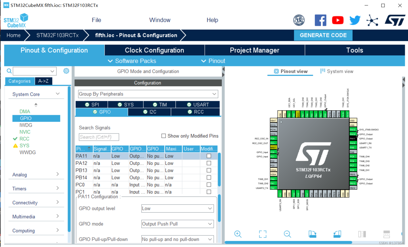
我们常用STM32CubeMX配置GPIO
而stm32CubeMX是通过HAL库来控制GPIO的
下面会通过详解HAL库中的具体代码解释这些寄存器
一、输入输出
输出:
void HAL_GPIO_WritePin(GPIO_TypeDef *GPIOx, uint16_t GPIO_Pin, GPIO_PinState PinState)
{
  /* Check the parameters */
  assert_param(IS_GPIO_PIN(GPIO_Pin));
  assert_param(IS_GPIO_PIN_ACTION(PinState));

  if (PinState != GPIO_PIN_RESET)
  {
    GPIOx->BSRR = GPIO_Pin;
  }
  else
  {
    GPIOx->BSRR = (uint32_t)GPIO_Pin << 16u;
  }
}
如果输出1,则在BSRR对应位置1,如果输出0,则在BSRR对应位+8置1,单片机会根据BSRR修改ODR从而输出指定信号。
输入:
GPIO_PinState HAL_GPIO_ReadPin(GPIO_TypeDef *GPIOx, uint16_t GPIO_Pin)
{
  GPIO_PinState bitstatus;

  /* Check the parameters */
  assert_param(IS_GPIO_PIN(GPIO_Pin));

  if ((GPIOx->IDR & GPIO_Pin) != (uint32_t)GPIO_PIN_RESET)
  {
    bitstatus = GPIO_PIN_SET;
  }
  else
  {
    bitstatus = GPIO_PIN_RESET;
  }
  return bitstatus;
}
如果输入1,那么IDR寄存器对应位就会置1,如果为0则置0.
还有一个翻转引脚输出:
void HAL_GPIO_TogglePin(GPIO_TypeDef *GPIOx, uint16_t GPIO_Pin)
{
  uint32_t odr;

  /* Check the parameters */
  assert_param(IS_GPIO_PIN(GPIO_Pin));

  /* get current Ouput Data Register value */
  odr = GPIOx->ODR;

  /* Set selected pins that were at low level, and reset ones that were high */
  GPIOx->BSRR = ((odr & GPIO_Pin) << GPIO_NUMBER) | (~odr & GPIO_Pin);
}
如果原先输出1则现在输出0,如果原先输出0则现在输出1.
二、初始化
初始化的过程大概是:
时钟使能->初始化输出(高低电平)->初始化其他配置
代码:
void MX_GPIO_Init(void)
{

  GPIO_InitTypeDef GPIO_InitStruct = {0};

  /* GPIO Ports Clock Enable */
  __HAL_RCC_GPIOD_CLK_ENABLE();
  __HAL_RCC_GPIOA_CLK_ENABLE();
  __HAL_RCC_GPIOB_CLK_ENABLE();
  __HAL_RCC_GPIOC_CLK_ENABLE();

  /*Configure GPIO pin Output Level */
  HAL_GPIO_WritePin(GPIOB, GPIO_PIN_13|GPIO_PIN_14, GPIO_PIN_RESET);

  /*Configure GPIO pin Output Level */
  HAL_GPIO_WritePin(GPIOA, GPIO_PIN_11|GPIO_PIN_12, GPIO_PIN_RESET);

  /*Configure GPIO pin Output Level */
  HAL_GPIO_WritePin(GPIOD, GPIO_PIN_2, GPIO_PIN_RESET);

  /*Configure GPIO pins : PB13 PB14 */
  GPIO_InitStruct.Pin = GPIO_PIN_13|GPIO_PIN_14;
  GPIO_InitStruct.Mode = GPIO_MODE_OUTPUT_PP;
  GPIO_InitStruct.Pull = GPIO_NOPULL;
  GPIO_InitStruct.Speed = GPIO_SPEED_FREQ_LOW;
  HAL_GPIO_Init(GPIOB, &GPIO_InitStruct);

  /*Configure GPIO pins : PA11 PA12 */
  GPIO_InitStruct.Pin = GPIO_PIN_11|GPIO_PIN_12;
  GPIO_InitStruct.Mode = GPIO_MODE_OUTPUT_PP;
  GPIO_InitStruct.Pull = GPIO_NOPULL;
  GPIO_InitStruct.Speed = GPIO_SPEED_FREQ_LOW;
  HAL_GPIO_Init(GPIOA, &GPIO_InitStruct);

  /*Configure GPIO pin : PD2 */
  GPIO_InitStruct.Pin = GPIO_PIN_2;
  GPIO_InitStruct.Mode = GPIO_MODE_OUTPUT_PP;
  GPIO_InitStruct.Pull = GPIO_NOPULL;
  GPIO_InitStruct.Speed = GPIO_SPEED_FREQ_LOW;
  HAL_GPIO_Init(GPIOD, &GPIO_InitStruct);

}
时钟使能在后面的文章中再详细说明
初始化输出前面已经说过
而这个“其他配置”相对复杂(或者说过于复杂),HAL库中的代码是这样的:
void HAL_GPIO_Init(GPIO_TypeDef  *GPIOx, GPIO_InitTypeDef *GPIO_Init)
{
  uint32_t position = 0x00u;
  uint32_t ioposition;
  uint32_t iocurrent;
  uint32_t temp;
  uint32_t config = 0x00u;
  __IO uint32_t *configregister; /* Store the address of CRL or CRH register based on pin number */
  uint32_t registeroffset;       /* offset used during computation of CNF and MODE bits placement inside CRL or CRH register */

  /* Check the parameters */
  assert_param(IS_GPIO_ALL_INSTANCE(GPIOx));
  assert_param(IS_GPIO_PIN(GPIO_Init->Pin));
  assert_param(IS_GPIO_MODE(GPIO_Init->Mode));

  /* Configure the port pins */
  while (((GPIO_Init->Pin) >> position) != 0x00u)
  {
    /* Get the IO position */
    ioposition = (0x01uL << position);

    /* Get the current IO position */
    iocurrent = (uint32_t)(GPIO_Init->Pin) & ioposition;

    if (iocurrent == ioposition)
    {
      /* Check the Alternate function parameters */
      assert_param(IS_GPIO_AF_INSTANCE(GPIOx));

      /* Based on the required mode, filling config variable with MODEy[1:0] and CNFy[3:2] corresponding bits */
      switch (GPIO_Init->Mode)
      {
        /* If we are configuring the pin in OUTPUT push-pull mode */
        case GPIO_MODE_OUTPUT_PP:
          /* Check the GPIO speed parameter */
          assert_param(IS_GPIO_SPEED(GPIO_Init->Speed));
          config = GPIO_Init->Speed + GPIO_CR_CNF_GP_OUTPUT_PP;
          break;

        /* If we are configuring the pin in OUTPUT open-drain mode */
        case GPIO_MODE_OUTPUT_OD:
          /* Check the GPIO speed parameter */
          assert_param(IS_GPIO_SPEED(GPIO_Init->Speed));
          config = GPIO_Init->Speed + GPIO_CR_CNF_GP_OUTPUT_OD;
          break;

        /* If we are configuring the pin in ALTERNATE FUNCTION push-pull mode */
        case GPIO_MODE_AF_PP:
          /* Check the GPIO speed parameter */
          assert_param(IS_GPIO_SPEED(GPIO_Init->Speed));
          config = GPIO_Init->Speed + GPIO_CR_CNF_AF_OUTPUT_PP;
          break;

        /* If we are configuring the pin in ALTERNATE FUNCTION open-drain mode */
        case GPIO_MODE_AF_OD:
          /* Check the GPIO speed parameter */
          assert_param(IS_GPIO_SPEED(GPIO_Init->Speed));
          config = GPIO_Init->Speed + GPIO_CR_CNF_AF_OUTPUT_OD;
          break;

        /* If we are configuring the pin in INPUT (also applicable to EVENT and IT mode) */
        case GPIO_MODE_INPUT:
        case GPIO_MODE_IT_RISING:
        case GPIO_MODE_IT_FALLING:
        case GPIO_MODE_IT_RISING_FALLING:
        case GPIO_MODE_EVT_RISING:
        case GPIO_MODE_EVT_FALLING:
        case GPIO_MODE_EVT_RISING_FALLING:
          /* Check the GPIO pull parameter */
          assert_param(IS_GPIO_PULL(GPIO_Init->Pull));
          if (GPIO_Init->Pull == GPIO_NOPULL)
          {
            config = GPIO_CR_MODE_INPUT + GPIO_CR_CNF_INPUT_FLOATING;
          }
          else if (GPIO_Init->Pull == GPIO_PULLUP)
          {
            config = GPIO_CR_MODE_INPUT + GPIO_CR_CNF_INPUT_PU_PD;

            /* Set the corresponding ODR bit */
            GPIOx->BSRR = ioposition;
          }
          else /* GPIO_PULLDOWN */
          {
            config = GPIO_CR_MODE_INPUT + GPIO_CR_CNF_INPUT_PU_PD;

            /* Reset the corresponding ODR bit */
            GPIOx->BRR = ioposition;
          }
          break;

        /* If we are configuring the pin in INPUT analog mode */
        case GPIO_MODE_ANALOG:
          config = GPIO_CR_MODE_INPUT + GPIO_CR_CNF_ANALOG;
          break;

        /* Parameters are checked with assert_param */
        default:
          break;
      }

      /* Check if the current bit belongs to first half or last half of the pin count number
       in order to address CRH or CRL register*/
      configregister = (iocurrent < GPIO_PIN_8) ? &GPIOx->CRL     : &GPIOx->CRH;
      registeroffset = (iocurrent < GPIO_PIN_8) ? (position << 2u) : ((position - 8u) << 2u);

      /* Apply the new configuration of the pin to the register */
      MODIFY_REG((*configregister), ((GPIO_CRL_MODE0 | GPIO_CRL_CNF0) << registeroffset), (config << registeroffset));

      /*--------------------- EXTI Mode Configuration ------------------------*/
      /* Configure the External Interrupt or event for the current IO */
      if ((GPIO_Init->Mode & EXTI_MODE) == EXTI_MODE)
      {
        /* Enable AFIO Clock */
        __HAL_RCC_AFIO_CLK_ENABLE();
        temp = AFIO->EXTICR[position >> 2u];
        CLEAR_BIT(temp, (0x0Fu) << (4u * (position & 0x03u)));
        SET_BIT(temp, (GPIO_GET_INDEX(GPIOx)) << (4u * (position & 0x03u)));
        AFIO->EXTICR[position >> 2u] = temp;


        /* Configure the interrupt mask */
        if ((GPIO_Init->Mode & GPIO_MODE_IT) == GPIO_MODE_IT)
        {
          SET_BIT(EXTI->IMR, iocurrent);
        }
        else
        {
          CLEAR_BIT(EXTI->IMR, iocurrent);
        }

        /* Configure the event mask */
        if ((GPIO_Init->Mode & GPIO_MODE_EVT) == GPIO_MODE_EVT)
        {
          SET_BIT(EXTI->EMR, iocurrent);
        }
        else
        {
          CLEAR_BIT(EXTI->EMR, iocurrent);
        }

        /* Enable or disable the rising trigger */
        if ((GPIO_Init->Mode & RISING_EDGE) == RISING_EDGE)
        {
          SET_BIT(EXTI->RTSR, iocurrent);
        }
        else
        {
          CLEAR_BIT(EXTI->RTSR, iocurrent);
        }

        /* Enable or disable the falling trigger */
        if ((GPIO_Init->Mode & FALLING_EDGE) == FALLING_EDGE)
        {
          SET_BIT(EXTI->FTSR, iocurrent);
        }
        else
        {
          CLEAR_BIT(EXTI->FTSR, iocurrent);
        }
      }
    }

	position++;
  }
}
程序会通过position寻找被初始化的端口号(这其实是不必要的,如果不用HAL库显然可以写出更精简且高效的算法),随后会配置模式、频率并写入对应的寄存器。
写入寄存器的命令用的是:
#define SET_BIT(REG, BIT)     ((REG) |= (BIT))

#define CLEAR_BIT(REG, BIT)   ((REG) &= ~(BIT))

#define READ_BIT(REG, BIT)    ((REG) & (BIT))

#define CLEAR_REG(REG)        ((REG) = (0x0))

#define WRITE_REG(REG, VAL)   ((REG) = (VAL))

#define READ_REG(REG)         ((REG))

#define MODIFY_REG(REG, CLEARMASK, SETMASK)  WRITE_REG((REG), (((READ_REG(REG)) & (~(CLEARMASK))) | (SETMASK)))

#define POSITION_VAL(VAL)     (__CLZ(__RBIT(VAL)))
本质上还是位运算,即通过修改对应位上的0/1数据来控制端口。
三、中断
HAL库提供了一个中断接口
void HAL_GPIO_EXTI_IRQHandler(uint16_t GPIO_Pin)
{
  /* EXTI line interrupt detected */
  if (__HAL_GPIO_EXTI_GET_IT(GPIO_Pin) != 0x00u)
  {
    __HAL_GPIO_EXTI_CLEAR_IT(GPIO_Pin);
    HAL_GPIO_EXTI_Callback(GPIO_Pin);
  }
}
对应一个中断回调函数
__weak void HAL_GPIO_EXTI_Callback(uint16_t GPIO_Pin)
{
  /* Prevent unused argument(s) compilation warning */
  UNUSED(GPIO_Pin);
  /* NOTE: This function Should not be modified, when the callback is needed,
           the HAL_GPIO_EXTI_Callback could be implemented in the user file
   */
}
个人感觉用的不多,也没什么好解释的。
综上,单片机的GPIO大多是通过寄存器控制的,而HAL库主要是封装了复杂的对寄存器的操作,
只给我们留出来一些简单的接口。事实上,从上面的分析可以发现HAL库代码的效率并不高,有时
不如我们自己编写的代码,但对于初学者来说,这样的封装大大降低了学习的难度。至于如何取舍
还得看实际应用的需要。