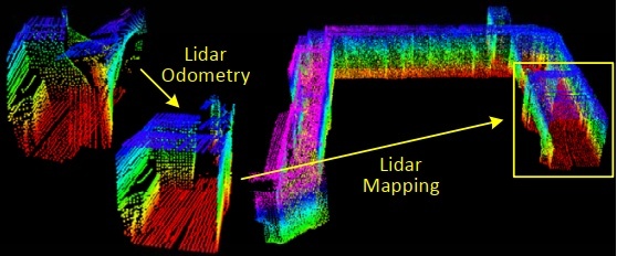
本章记录loam的第三部分地图构建,仍然从main函数看起。
首先订阅/laser_cloud_corner_last和/laser_cloud_surf_last特征点云,订阅特征点云对应的全局位姿/laser_odom_to_init。然后订阅第二部分laserOdometry处理后的实时点云/velodyne_cloud_3,订阅/imu/data用于读取imu姿态角。最后发布/laser_cloud_surround和/velodyne_cloud_registered和/aft_mapped_to_init。
点云回调函数将点云rosmsgs格式转换为pcl格式,全局位姿回调将位姿信息保存在transformSum中,imu回调函数保存时间戳和roll/pitch信息。
建图环节将整个空间三维区域划分为laserCloudNum个子cube,从while循环开始看。
while (status) {
  ros::spinOnce();
  if (newLaserCloudCornerLast && newLaserCloudSurfLast && newLaserCloudFullRes && newLaserOdometry &&
      fabs(timeLaserCloudCornerLast - timeLaserOdometry) < 0.005 &&
      fabs(timeLaserCloudSurfLast - timeLaserOdometry) < 0.005 &&
      fabs(timeLaserCloudFullRes - timeLaserOdometry) < 0.005) {
    newLaserCloudCornerLast = false;
    newLaserCloudSurfLast = false;
    newLaserCloudFullRes = false;
    newLaserOdometry = false;
    frameCount++;
while循环首先进行一次回调,并确保时间一致性,然后重置标志位,帧数量+1。
后续涉及到transformAssociateToMap()函数,先分析。该函数首先将每次地图匹配前的位姿transformBefMapped与订阅的初始位姿transformSum之间的平移偏差按照yxz顺序旋转到transformSum坐标系方向,得到transformIncre。然后和第二部分PluginIMURotation()函数一样,通过地图匹配前后的姿态transformBefMapped/transformAftMapped以及初始姿态transformSum计算得到地图匹配时transformTobeMapped的姿态。计算原理如下图。
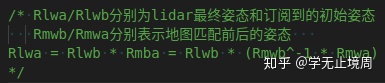
最后将transformIncre位置偏差转换至transformTobeMapped坐标系方向,由transformAftMapped位置信息减去转换后的偏差得到transformTobeMapped位置信息。
下面回到main函数中:
/*坐标变换*/
if (frameCount >= stackFrameNum) {
  transformAssociateToMap();   //地图匹配坐标转换
  int laserCloudCornerLastNum = laserCloudCornerLast->points.size();
  for (int i = 0; i < laserCloudCornerLastNum; i++) {
    pointAssociateToMap(&laserCloudCornerLast->points[i], &pointSel);
    laserCloudCornerStack2->push_back(pointSel);
  }
  int laserCloudSurfLastNum = laserCloudSurfLast->points.size();  //面特征点
  for (int i = 0; i < laserCloudSurfLastNum; i++) {
    pointAssociateToMap(&laserCloudSurfLast->points[i], &pointSel);
    laserCloudSurfStack2->push_back(pointSel);
  }
}
上述代码首先调用transformAssociateToMap()函数进行地图匹配相关位姿信息变换,接着针对边特征点和面特征点调用pointAssociateToMap()函数,将pi坐标点通过transformTobeMapped转换到全局坐标系,将处理完的特征点保存到点云。
/*优化处理  找当前估计的lidar位姿属于哪个cube,I/J/K对应cube的索引*/
if (frameCount >= stackFrameNum) {
  frameCount = 0;
  //当前lidar坐标系{L}y轴一点(0,10,0)
  PointType pointOnYAxis;
  pointOnYAxis.x = 0.0;
  pointOnYAxis.y = 10.0;
  pointOnYAxis.z = 0.0;
  pointAssociateToMap(&pointOnYAxis, &pointOnYAxis); //转换到全局坐标系
  //cube中心位置索引
  int centerCubeI = int((transformTobeMapped[3] + 25.0) / 50.0) + laserCloudCenWidth;     //[-25,25)->10  [25,75)->11
  int centerCubeJ = int((transformTobeMapped[4] + 25.0) / 50.0) + laserCloudCenHeight;    //[-25,25)->5  [25,75)->6
  int centerCubeK = int((transformTobeMapped[5] + 25.0) / 50.0) + laserCloudCenDepth;     //[-25,25)->10  [25,75)->11
  if (transformTobeMapped[3] + 25.0 < 0) centerCubeI--;
  if (transformTobeMapped[4] + 25.0 < 0) centerCubeJ--;
  if (transformTobeMapped[5] + 25.0 < 0) centerCubeK--;
上述代码首先在当前帧坐标系中定义一个坐标点pointOnYxis,并转换到全局坐标系。接着计算当前帧位姿所在的cube索引,如果是在负区间则索引需要减1。
//如果当前帧lidar位姿对应的cube在整个大cube边缘则将索引向中心方向挪动一个单位
while (centerCubeI < 3) {   //width方向的小端   将帧cube指针向中心方向平移
  for (int j = 0; j < laserCloudHeight; j++) {
    for (int k = 0; k < laserCloudDepth; k++) {
      int i = laserCloudWidth - 1;
      pcl::PointCloud<PointType>::Ptr laserCloudCubeCornerPointer = //指向width最大处的cube点云
               laserCloudCornerArray[i + laserCloudWidth * j + laserCloudWidth * laserCloudHeight * k];
      pcl::PointCloud<PointType>::Ptr laserCloudCubeSurfPointer =
               laserCloudSurfArray[i + laserCloudWidth * j + laserCloudWidth * laserCloudHeight * k];
      for (; i >= 1; i--) {  //将cube由width大段开始依次向增大方向移动一个单位
        laserCloudCornerArray[i + laserCloudWidth * j + laserCloudWidth * laserCloudHeight * k] =
        laserCloudCornerArray[i - 1 + laserCloudWidth*j + laserCloudWidth * laserCloudHeight * k];
        laserCloudSurfArray[i + laserCloudWidth * j + laserCloudWidth * laserCloudHeight * k] =
        laserCloudSurfArray[i - 1 + laserCloudWidth * j + laserCloudWidth * laserCloudHeight * k];
      }
      //移动后最小width索引指向原来最大width处
      laserCloudCornerArray[i + laserCloudWidth * j + laserCloudWidth * laserCloudHeight * k] =
              laserCloudCubeCornerPointer;
      laserCloudSurfArray[i + laserCloudWidth * j + laserCloudWidth * laserCloudHeight * k] =
              laserCloudCubeSurfPointer;
      laserCloudCubeCornerPointer->clear();
      laserCloudCubeSurfPointer->clear();
    }
  }
  centerCubeI++;      //帧所在的cube在width方向相应增大一个单位
  laserCloudCenWidth++;    //中心位置索引同样增大
}
得到当前帧cube索引后需要分析判断,上段代码对cube进行width方向判断。如果当前帧cube索引位于width小端边界(<3),则从大端-1开始依次向大端平移一个单位,其中最大端的索引赋给移动前的最小端,全部索引移动完后对应的当前帧索引centerCubeI和中心索引laserCloudCenWidth都需要+1。上述代码针对的是width小端,同样的,width大端/height小端和大端/depth小端和大端需要进行类似判断。最终,得到当前帧全局位姿在cube中经过处理的索引。
//在当前帧lidar位姿所在cube附近5×5×5的邻域cube内找有效的cube
int laserCloudValidNum = 0;     //125个领域cube中有效领域的num
int laserCloudSurroundNum = 0;
for (int i = centerCubeI - 2; i <= centerCubeI + 2; i++) {// centerCube为当前帧所在cube的索引
  for (int j = centerCubeJ - 2; j <= centerCubeJ + 2; j++) {
    for (int k = centerCubeK - 2; k <= centerCubeK + 2; k++) {
      if (i >= 0 && i < laserCloudWidth &&          //在cube索引范围内
                  j >= 0 && j < laserCloudHeight &&
                  k >= 0 && k < laserCloudDepth) {
        //计算各邻域cube中心点坐标
        float centerX = 50.0 * (i - laserCloudCenWidth);
        float centerY = 50.0 * (j - laserCloudCenHeight);
        float centerZ = 50.0 * (k - laserCloudCenDepth);
        //取cube的8个顶点
        bool isInLaserFOV = false;
        for (int ii = -1; ii <= 1; ii += 2) {   //2X2X2=8
          for (int jj = -1; jj <= 1; jj += 2) {
            for (int kk = -1; kk <= 1; kk += 2) {
              float cornerX = centerX + 25.0 * ii;   //cube的8个顶点坐标
              float cornerY = centerY + 25.0 * jj;
              float cornerZ = centerZ + 25.0 * kk;
              float squaredSide1 = (transformTobeMapped[3] - cornerX)//当前帧lidar全局位姿与邻域cube顶点的距离平方
                                 * (transformTobeMapped[3] - cornerX)
                                 + (transformTobeMapped[4] - cornerY)
                                 * (transformTobeMapped[4] - cornerY)
                                 + (transformTobeMapped[5] - cornerZ)
                                 * (transformTobeMapped[5] - cornerZ);
              float squaredSide2 = (pointOnYAxis.x - cornerX) * (pointOnYAxis.x - cornerX) //当前帧中(0,10,0)与顶点距离方
                                 + (pointOnYAxis.y - cornerY) * (pointOnYAxis.y - cornerY)
                                 + (pointOnYAxis.z - cornerZ) * (pointOnYAxis.z - cornerZ);
              float check1 = 100.0 + squaredSide1 - squaredSide2
                           - 10.0 * sqrt(3.0) * sqrt(squaredSide1);
              float check2 = 100.0 + squaredSide1 - squaredSide2
                           + 10.0 * sqrt(3.0) * sqrt(squaredSide1);
              if (check1 < 0 && check2 > 0) {   //该cube的8个顶点只要有一个符合距离相关的条件,则该cube为有效邻域
                isInLaserFOV = true;
              }
            }
          }
        }
        if (isInLaserFOV) {  //当前lidar全局位姿的有效邻域cube在地图中的索引
          laserCloudValidInd[laserCloudValidNum] = i + laserCloudWidth * j
                   + laserCloudWidth * laserCloudHeight * k;
          laserCloudValidNum++;
        }
        // 125个领域cube索引(包括不符合距离条件的cube)
        laserCloudSurroundInd[laserCloudSurroundNum] = i + laserCloudWidth * j
                                     + laserCloudWidth * laserCloudHeight * k;
        laserCloudSurroundNum++;
      }
    }
  }
}
地图匹配是与当前帧位姿附近5*5*5个cube匹配,需要对这125个邻域cube分析。上述代码中首先计算子cube中心坐标,根据中心坐标计算其8个顶点,进而计算当前帧lidar全局坐标与邻域cube顶点的距离方squaredSide1以及前面定义的pointOnYxis与顶点的距离方。通过check1和check2判断当前邻域cube是否有效,此处判断条件设定不是很理解?如果满足判定条件,则当前cube为lidar全局位姿的有效邻域,保存对应的cube索引到laserCloudValidInd[],同时保存所有的125个邻域索引到laserCloudSurroundInd[]。
//拼接有效领域cube内的特征点云作为map点云用来匹配
laserCloudCornerFromMap->clear();
laserCloudSurfFromMap->clear();
for (int i = 0; i < laserCloudValidNum; i++) {    //有效的邻域cube
  *laserCloudCornerFromMap += *laserCloudCornerArray[laserCloudValidInd[i]]; //有效cube构成匹配地图
  *laserCloudSurfFromMap += *laserCloudSurfArray[laserCloudValidInd[i]];
}
int laserCloudCornerFromMapNum = laserCloudCornerFromMap->points.size(); //corner点云中特征点数量
int laserCloudSurfFromMapNum = laserCloudSurfFromMap->points.size();    //surf点云特征点数量

//将世界坐标系下当前帧特征点转到当前lidar坐标系下
int laserCloudCornerStackNum2 = laserCloudCornerStack2->points.size(); //当前帧边特征点个数
for (int i = 0; i < laserCloudCornerStackNum2; i++) {
  pointAssociateTobeMapped(&laserCloudCornerStack2->points[i], &laserCloudCornerStack2->points[i]);
}
int laserCloudSurfStackNum2 = laserCloudSurfStack2->points.size();        //面特征点
for (int i = 0; i < laserCloudSurfStackNum2; i++) {
  pointAssociateTobeMapped(&laserCloudSurfStack2->points[i], &laserCloudSurfStack2->points[i]);
}
上述代码首先将有效邻域cube点云拼接到laserCloudCornerFromMap和laserCloudCornerSurfFromMap,接着调用pointAssociateTobeMapped()函数将世界坐标系下的特征点云转换到lidar坐标系,此处世界坐标系点云来自于之前pointAssociateToMap()函数,但中间并没有对特征点云做别的操作,来回转换是否多余?
接着对lidar坐标系下特征点云进行了滤波处理,降低数据量。
至此,得到了lidar当前帧特征点云和附近的地图特征点云,后续利用kD树寻找邻近匹配点,从而构建点到线和点到面距离,这部分与前一章类似。差异在于,对于线特征点,帧间匹配时kd树是先查找当前帧特征点在前一帧的最邻近点,再在相邻线找次邻近点,从而构建点到直线距离;而地图匹配时是查找当前帧特征点的5个邻近点,再根据5个领近点的特征向量构建直线距离。
if (laserCloudCornerFromMapNum > 10 && laserCloudSurfFromMapNum > 100) { //地图特征点足够多
  kdtreeCornerFromMap->setInputCloud(laserCloudCornerFromMap);//地图特征点云存入kd树
  kdtreeSurfFromMap->setInputCloud(laserCloudSurfFromMap);
  for (int iterCount = 0; iterCount < 10; iterCount++) {     //迭代次数
    laserCloudOri->clear();
    coeffSel->clear();
    //当前帧边特征点   地图KD树搜索当前帧边特征点最邻近的5个点
    for (int i = 0; i < laserCloudCornerStackNum; i++) {
      pointOri = laserCloudCornerStack->points[i];
      pointAssociateToMap(&pointOri, &pointSel);     //特征点转到全局坐标系下
      kdtreeCornerFromMap->nearestKSearch(pointSel, 5, pointSearchInd, pointSearchSqDis);

      if (pointSearchSqDis[4] < 1.0) {   //第5远的点与当前特征点的距离在阈值内
        float cx = 0;
        float cy = 0;
        float cz = 0;
        for (int j = 0; j < 5; j++) {
          cx += laserCloudCornerFromMap->points[pointSearchInd[j]].x;
          cy += laserCloudCornerFromMap->points[pointSearchInd[j]].y;
          cz += laserCloudCornerFromMap->points[pointSearchInd[j]].z;
        }
        cx /= 5;        //求出5个邻近点坐标均值
        cy /= 5;
        cz /= 5;

        float a11 = 0;
        float a12 = 0;
        float a13 = 0;
        float a22 = 0;
        float a23 = 0;
        float a33 = 0;
        for (int j = 0; j < 5; j++) {    //构建协方差矩阵
          float ax = laserCloudCornerFromMap->points[pointSearchInd[j]].x - cx;
          float ay = laserCloudCornerFromMap->points[pointSearchInd[j]].y - cy;
          float az = laserCloudCornerFromMap->points[pointSearchInd[j]].z - cz;
          a11 += ax * ax;
          a12 += ax * ay;
          a13 += ax * az;
          a22 += ay * ay;
          a23 += ay * az;
          a33 += az * az;
        }
        a11 /= 5;
        a12 /= 5;
        a13 /= 5;
        a22 /= 5;
        a23 /= 5;
        a33 /= 5;

      matA1.at<float>(0, 0) = a11;      //3X3协方差矩阵
      matA1.at<float>(0, 1) = a12;
      matA1.at<float>(0, 2) = a13;
      matA1.at<float>(1, 0) = a12;
      matA1.at<float>(1, 1) = a22;
      matA1.at<float>(1, 2) = a23;
      matA1.at<float>(2, 0) = a13;
      matA1.at<float>(2, 1) = a23;
      matA1.at<float>(2, 2) = a33;

      cv::eigen(matA1, matD1, matV1);   //特征根matD1,对应的特征向量matV1

      if (matD1.at<float>(0, 0) > 3 * matD1.at<float>(0, 1)) {
        float x0 = pointSel.x;     //x0为当前帧特征点
        float y0 = pointSel.y;
        float z0 = pointSel.z;
        //根据特征向量的方向构建x1和x2,两者连线代表最近点构成的直线
        float x1 = cx + 0.1 * matV1.at<float>(0, 0);
        float y1 = cy + 0.1 * matV1.at<float>(0, 1);
        float z1 = cz + 0.1 * matV1.at<float>(0, 2);
        float x2 = cx - 0.1 * matV1.at<float>(0, 0);
        float y2 = cy - 0.1 * matV1.at<float>(0, 1);
        float z2 = cz - 0.1 * matV1.at<float>(0, 2);
上述代码首先将特征地图存入kd树,设置迭代循环。对于边特征点,先转到全局坐标系,再在KD树中搜索5个邻近点。接着求5个邻域点的均值点,并构建协方差矩阵,进行特征值分解,通过最大特征值对应的特征向量构建直线,最终得到与前一章帧间匹配类似的当前特征帧特征点x0,匹配的直线点x1/x2。后续构建点到直线的距离ld2及求偏导la/lb/lc与前一章帧间匹配完全一致。
对于面特征点,上一章帧间匹配通过kd树查找3个最邻近点构成平面,然后通过论文中公式计算点到面的距离。本章地图匹配则仍然是先搜索5个最近点,由于这5个点在一个平面上,代码中直接通过矩阵运算求解5个点构成平面的法向量。
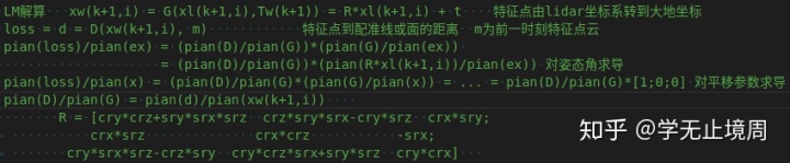
得到当前帧线特征点和面特征点与地图配准后,构建loss函数求解,构建损失函数原理如下:
for (int i = 0; i < laserCloudSelNum; i++) {
  pointOri = laserCloudOri->points[i];    //当前帧特征点
  coeff = coeffSel->points[i];            //对应距离的偏导
  //loss函数对欧拉角求偏导
  //pian(loss)/pian(ex)
  float arx = (crx*sry*srz*pointOri.x + crx*crz*sry*pointOri.y - srx*sry*pointOri.z) * coeff.x
            + (-srx*srz*pointOri.x - crz*srx*pointOri.y - crx*pointOri.z) * coeff.y
            + (crx*cry*srz*pointOri.x + crx*cry*crz*pointOri.y - cry*srx*pointOri.z) * coeff.z;

  float ary = ((cry*srx*srz - crz*sry)*pointOri.x
            + (sry*srz + cry*crz*srx)*pointOri.y + crx*cry*pointOri.z) * coeff.x
            + ((-cry*crz - srx*sry*srz)*pointOri.x
            + (cry*srz - crz*srx*sry)*pointOri.y - crx*sry*pointOri.z) * coeff.z;

  float arz = ((crz*srx*sry - cry*srz)*pointOri.x + (-cry*crz-srx*sry*srz)*pointOri.y)*coeff.x
            + (crx*crz*pointOri.x - crx*srz*pointOri.y) * coeff.y
            + ((sry*srz + cry*crz*srx)*pointOri.x + (crz*sry-cry*srx*srz)*pointOri.y)*coeff.z;

  matA.at<float>(i, 0) = arx;
  matA.at<float>(i, 1) = ary;
  matA.at<float>(i, 2) = arz;
  matA.at<float>(i, 3) = coeff.x;
  matA.at<float>(i, 4) = coeff.y;
  matA.at<float>(i, 5) = coeff.z;
  matB.at<float>(i, 0) = -coeff.intensity;
}
上述代码中arx/ary/arz即为loss函数对姿态角的偏导,coeff.x刚好为loss函数对平移x的偏导,之后构建雅克比矩阵matA。与laserOdometry章节一样,采用QR分解得到transformTobeMapped每次迭代增量matX,满足收敛条件则退出迭代。迭代后调用transformUpdate()函数更新位姿变量。
//更新位姿相关向量
void transformUpdate()
{
  if (imuPointerLast >= 0) {   //有imu数据
    float imuRollLast = 0, imuPitchLast = 0;
    while (imuPointerFront != imuPointerLast) {//front变量调整到与last变量一致,或者到激光点最近的imu数据位置
      if (timeLaserOdometry + scanPeriod < imuTime[imuPointerFront]) {
        break;
      }
      imuPointerFront = (imuPointerFront + 1) % imuQueLength;
    }

    if (timeLaserOdometry + scanPeriod > imuTime[imuPointerFront]) { // 当前雷达帧time大于imu数据time
      imuRollLast = imuRoll[imuPointerFront];
      imuPitchLast = imuPitch[imuPointerFront];
    } else {      //否则插值imu相邻的back与front数据
      int imuPointerBack = (imuPointerFront + imuQueLength - 1) % imuQueLength;
      float ratioFront = (timeLaserOdometry + scanPeriod - imuTime[imuPointerBack])
                       / (imuTime[imuPointerFront] - imuTime[imuPointerBack]);
      float ratioBack = (imuTime[imuPointerFront] - timeLaserOdometry - scanPeriod)
                       / (imuTime[imuPointerFront] - imuTime[imuPointerBack]);
      imuRollLast = imuRoll[imuPointerFront] * ratioFront + imuRoll[imuPointerBack] * ratioBack;
      imuPitchLast = imuPitch[imuPointerFront] * ratioFront + imuPitch[imuPointerBack] * ratioBack;
    }

    transformTobeMapped[0] = 0.998 * transformTobeMapped[0] + 0.002 * imuPitchLast;    //匹配后的当前帧lidar位姿加入惯导数据影响
    transformTobeMapped[2] = 0.998 * transformTobeMapped[2] + 0.002 * imuRollLast;
  }
  for (int i = 0; i < 6; i++) {
    transformBefMapped[i] = transformSum[i];      // 初始位姿
    transformAftMapped[i] = transformTobeMapped[i];    //补偿后的位姿为最终位姿
  }
}
transformUpdate()函数首先进行imu和帧间匹配位姿的时间同步,然后赋值imuRollLast和imuPitchLast,并融合了地图匹配位姿和imu位姿。最后,将订阅的帧间匹配位姿赋值给transformBefMapped,将融合后位姿赋给最终的transformAftMapped。
/*前面完成了当前帧与地图的匹配优化,现在将当前帧特征点云保存在地图中
//当前帧边特征点
for (int i = 0; i < laserCloudCornerStackNum; i++) {
  pointAssociateToMap(&laserCloudCornerStack->points[i], &pointSel);//转换到全局坐标系

  int cubeI = int((pointSel.x + 25.0) / 50.0) + laserCloudCenWidth; //特征点width方向索引
  int cubeJ = int((pointSel.y + 25.0) / 50.0) + laserCloudCenHeight;
  int cubeK = int((pointSel.z + 25.0) / 50.0) + laserCloudCenDepth;

  if (pointSel.x + 25.0 < 0) cubeI--;
  if (pointSel.y + 25.0 < 0) cubeJ--;
  if (pointSel.z + 25.0 < 0) cubeK--;

  if (cubeI >= 0 && cubeI < laserCloudWidth &&
              cubeJ >= 0 && cubeJ < laserCloudHeight &&
              cubeK >= 0 && cubeK < laserCloudDepth) {
    int cubeInd = cubeI + laserCloudWidth * cubeJ + laserCloudWidth * laserCloudHeight * cubeK;  //边特征点对应的cube索引号
    laserCloudCornerArray[cubeInd]->push_back(pointSel);       //特征点存入cube中
  }
}
完成当前帧特征点与与地图的匹配优化后,需要将当前帧特征点云加入地图中。上述是当前帧的边特征点云,首先将边特征点通过优化后的位姿转换到全局坐标系,然后计算应对的cube索引cubeInd,最后将特征点pointSel加入laserCloudCornerArray[cubeInd]中。平面特征点处理与线特征点一样,不再赘述。
//对当前帧而言,存在有限个邻域cube用于配准
for (int i = 0; i < laserCloudValidNum; i++) {  //对当前帧有效的邻域cube数量
  int ind = laserCloudValidInd[i];

  laserCloudCornerArray2[ind]->clear();      //对cube内边特征点云降采样
  downSizeFilterCorner.setInputCloud(laserCloudCornerArray[ind]);
  downSizeFilterCorner.filter(*laserCloudCornerArray2[ind]);

  laserCloudSurfArray2[ind]->clear();            //对cube内面特征点云降采样
  downSizeFilterSurf.setInputCloud(laserCloudSurfArray[ind]);
  downSizeFilterSurf.filter(*laserCloudSurfArray2[ind]);

  pcl::PointCloud<PointType>::Ptr laserCloudTemp = laserCloudCornerArray[ind];  //最终cube内特征点云存储在laserCloudCornerArray中
  laserCloudCornerArray[ind] = laserCloudCornerArray2[ind];
  laserCloudCornerArray2[ind] = laserCloudTemp;

  laserCloudTemp = laserCloudSurfArray[ind];
  laserCloudSurfArray[ind] = laserCloudSurfArray2[ind];
  laserCloudSurfArray2[ind] = laserCloudTemp;
}
特征点插入地图后,需要对地图进行降采样,上述代码对当前帧有效邻域cube进行了滤波操作。
最后发布各种消息,代码中每5帧发布一次。首先发布当前帧附近laserCloudSurroundNum个cube中的特征点云,同样需要滤波处理。接着发布当前帧点云,需通过优化后的位姿转换到全局坐标系。最后发布优化后的lidar位姿并tf广播。
至此,完成了loam的第三部分地图laserMapping代码解析。地图匹配章节主要是在前一章帧间匹配基础上优化lidar位姿,达到更好的里程计效果。