基于脉动阵列实现矩阵卷积(FPGA)
摸了很久?,才想起来还有一篇脉动阵列实现简单矩阵卷积的东西没写。今天就来通过google的tpu结构,来谈一下通过脉动阵列实现矩阵卷积,并且来写一个简单的3x3矩阵的2x2卷积核的卷积。
脉动阵列
脉动阵列的基本原理在之前的一篇已经写的很清楚了。可以翻到前面看一下脉动阵列的加速矩阵乘法的文章。这里就不赘述了。
脉动阵列实现矩阵卷积
其实这个概念已经是比较成熟了的东西了,谷歌的TPU架构让这个老东西回到大众视野里(虽然已经是18年的东西了),当时去年Google也出了一款tpu的芯片,还是值得期待一下的。
关于卷积大家应该很直观就能想象到下面这副图:
看动态图是比较简单的,但是实际上硬件执行卷积行为是需要花费额外的时钟周期和资源去做这件事情,不断进行乘加、累加操作,占用资源比较大。Google的工程师们想到可以通过脉动阵列来解决这个问题,使得数据重复读取的次数降低,让数据流动起来。
实现卷积阵列的原理,这里可以参考【模型推理】一文看懂 Google TPU 脉动阵列加速卷积计算原理这篇文章中的推理图,讲的是比较详细的。我这里就讲如何实现3x3矩阵的2x2卷积。
首先我们需要确定脉动阵列单元的功能,首先1是完成乘加和累加的操作,然后是输出前面的运算结果,并且将参与运算的数据流传出,以方便后续阵列单元的搭建。我们确定了要求,那么就可以动手写一个乘法器之后搭建阵列单元了。
这里直接上代码
`timescale 1ns/1ns
module be(
  input       clk,
  input       rstn,
  input       clear,
  input [15:0] data_in,
  input [3:0] kernel,
  input [3:0] shift_in,
  output reg [15:0] data_out,
  output reg [3:0] shift_out
);
wire [7:0] data_tmp;

always @(posedge clk or negedge rstn)
begin
if(!rstn)
begin
  data_out<=16'd0;
  shift_out<=4'd0;
end
else
begin
  if(clear)
    begin
      data_out<=16'd0;
      shift_out<='d0;
    end
    else
    begin
      data_out<=data_tmp+data_in;
      shift_out<=shift_in;
    end
end
end
  multi_pipe u_multi_pipe(
      .clk	(clk),
      .rst_n	(rstn),
      .mul_a	(kernel),
      .mul_b	(shift_in),
      .mul_out (data_tmp)
  );

  endmodule
搭建完阵列单元之后,就可以编写testbench来测试效果了。前面参考文章里讲的需要按照卷积核权重来分配每个单元的数据输入,这里偷懒直接手动设置了,然后通过移位寄存器来实现输入,后面会再写一个输入矩阵然后分配序列(天,又开新坑)。代码里例化了4个阵列单元就可以实现输出。
向上代码:
`timescale 1ns/1ns
module tb_be();
reg clk;
reg rstn;
reg [3:0] shift_in [3:0];
wire [3:0] kernel;

wire [15:0] data_out;
wire [3:0] shift_out;

reg [15:0] line_data0;
reg [19:0] line_data1;
reg [23:0] line_data2;
reg [27:0] line_data3;
assign kernel= 4'd1;

initial begin
  clk<=1'd0;
  rstn<=1'd0;
  #(25)rstn<=1'd1;
end

always #(4) clk<=~clk;

reg [3:0] send_count;


always @(posedge clk or negedge rstn)
begin
  if(!rstn)
    begin
      shift_in[0]<=4'd0;
      shift_in[1]<=4'd0;
      shift_in[2]<=4'd0;
      shift_in[3]<=4'd0;
      line_data0<={4'd1,4'd2,4'd4,4'd5};
      line_data1<={4'd0,4'd2,4'd3,4'd5,4'd6};
      line_data2<={4'd0,4'd0,4'd4,4'd5,4'd7,4'd8};
      line_data3<={4'd0,4'd0,4'd0,4'd5,4'd6,4'd8,4'd9};
    end
    else
    begin
      shift_in[0]<=line_data0[15:12];
      line_data0<={line_data0[11:0],4'd0};

      shift_in[1]<=line_data1[19:16];
      line_data1<={line_data1[15:0],4'd0};

      shift_in[2]<=line_data2[23:20];
      line_data2<={line_data2[19:0],4'd0};

      shift_in[3]<=line_data3[27:24];
      line_data3<={line_data3[23:0],4'd0};
    end
end

wire [15:0] out_be [3:0];

be test_be_1(
 .clk (clk),
.rstn (rstn),
.clear (1'b0),
.data_in  (16'd0),
.kernel   (kernel),
.shift_in (shift_in[0]),
.data_out (out_be[0]),
.shift_out( )
);

be test_be_2(
 .clk (clk),
.rstn (rstn),
.clear (1'b0),
.data_in  (out_be[0]),
.kernel   (kernel),
.shift_in (shift_in[1]),
.data_out (out_be[1]),
.shift_out( )
);
be test_be_3(
 .clk (clk),
.rstn (rstn),
.clear (1'b0),
.data_in  (out_be[1]),
.kernel   (kernel),
.shift_in (shift_in[2]),
.data_out (out_be[2]),
.shift_out( )
);
be test_be_4(
 .clk (clk),
.rstn (rstn),
.clear (1'b0),
.data_in  (out_be[2]),
.kernel   (kernel),
.shift_in (shift_in[3]),
.data_out (out_be[3]),
.shift_out( )
);
endmodule
然后我们来看看仿真结果。
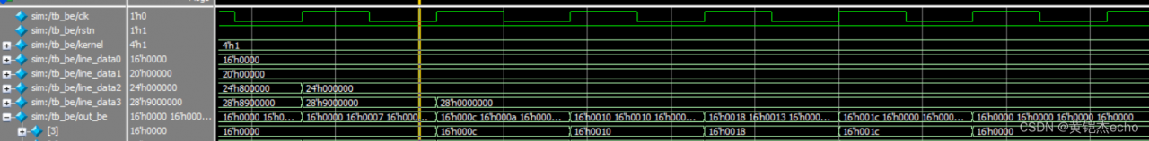
line_data是输入的信号,然后可以看到out_be[3]这一行中依次输出了 0x0c 0x10 0x18 0x1c,对应了矩阵卷积成功,可以验证得到脉动阵列实现了指定矩阵大小的卷积。
但是我们发现了一个问题,这里我们计算的实际上只是一个3x3的矩阵,并且卷积核大小也是只有2x2的,在实际运用中很少会有这么小的矩阵,如果是大型矩阵的话,首先输入序列的生成会比较麻烦(因为需要按卷积核权重展开),其次是需要更多的阵列单元,设若矩阵更大,卷积核更大,脉动阵列会过于庞大/畸形,笔者在想可以通过分割矩阵来实现,但是具体的方案还是没有想清楚,欢迎大家讨论。
接下来是一点牢骚,发现自己写技术面的东西很难往外扩展多新的东西出来,可能是对于写的东西不是很充分,下次需要再更多了解才能写的更好。另外就是后面的话应该会写一些密码学的东西,感觉是挺有趣的,但是写blog的话自己不怎么会画公式,估计出的会比较慢。
