1.首先创建RTL工程LED,然后create block design ,添加IP核,由于本实验使用的LED灯在设计上参照UG585手册,是PL端的资源,所以本实验是PS+PL。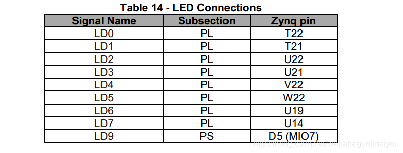
2.添加zynq的IP,然后自动连线。因为要访问LED,所以要添加AXI的IP(因为PS和PL之间的通信是通过AXI总线实现的) ,这些步骤其相当于配置一个CPU。现在在vivado中配置的是基础的硬件配置,属于PL;后面可以在SDK中对其进行软件编程,属于PS。具体的IP核的添加,见https://blog.csdn.net/weixin_42639919/article/details/81130581
这时候zynq的时钟已经自动连接,没接的时候一定要自己接上,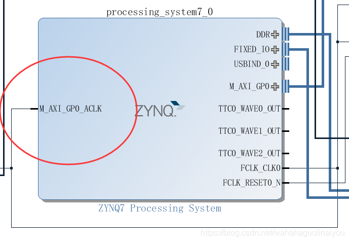
3.做好PL端的配置后,生成bit流,然后(include bitstream)导入到SDK。(具体包括,产生外部产品、生成顶层文件、Export 、lanuch to SDK)
3.在SDK中,等待硬件信息导入完成后,新建工程led,打开空工程。然后添加原文件led.c(单击led > 右键单击src > new > Source File)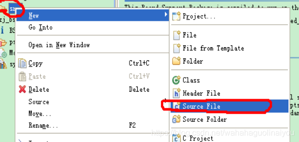
4.然后,编写led.c ,保存就是编译。程序如下:
#include "xparameters.h"        /* Peripheral parameters  */

#include "xgpio.h"              /* GPIO data struct and APIs */

#include "xil_printf.h"

#include "xil_cache.h"

#define GPIO_BITWIDTH   8       /* This is the width of the GPIO */

#define GPIO_DEVICE_ID   0//device id

#define LED_DELAY       10000000/* times delay*/

#define LED_MAX_BLINK   0x1     /* Number of times the LED Blinks */

#define LED_CHANNEL     1       /* GPIO channel*/

#define printf xil_printf   /* A smaller footprint printf */

XGpio Gpio; /* The Instance of the GPIO Driver */

XGpio GpioOutput; /* The driver instance for GPIO Device configured as O/P */


int GpioMarquee (u16 DeviceId, u32 GpioWidth)

{

    volatile int Delay;

    u32 LedBit;

    u32 LedLoop;

    int Status;

    /*

     * Initialize the GPIO driver so that it's ready to use,

     * specify the device ID that is generated in xparameters.h

     */

     Status = XGpio_Initialize(&GpioOutput, DeviceId);

    if (Status != XST_SUCCESS)

    {

        return XST_FAILURE;

     }

    //Set the direction for all signals to be outputs

     XGpio_SetDataDirection(&GpioOutput, LED_CHANNEL, 0x0);

    // Set the GPIO outputs to low

     XGpio_DiscreteWrite(&GpioOutput, LED_CHANNEL, 0x0);


    for (LedBit = 0x0; LedBit < GpioWidth; LedBit++)

    {

        for (LedLoop = 0; LedLoop < LED_MAX_BLINK; LedLoop++)

        {

            //Set the GPIO Output to High

            XGpio_DiscreteWrite(&GpioOutput, LED_CHANNEL,1 << LedBit);

            //Wait a small amount of time so the LED is visible

            for (Delay = 0; Delay < LED_DELAY;Delay++);

            //Clear the GPIO Output

            XGpio_DiscreteClear(&GpioOutput, LED_CHANNEL,1 << LedBit);

            // Wait a small amount of time so the LED is visible

            for (Delay = 0; Delay < LED_DELAY; Delay++);

          }

     }

    return XST_SUCCESS;

}

int main(void)

{//Application start

    /* loop forever*/

    int cnt=0;

    while(1)

    {

        u32 status;

        status = GpioMarquee (GPIO_DEVICE_ID,GPIO_BITWIDTH);

        if (status == 0)

        {

            printf("%d:SUCESS!.\r\n",cnt++);

            if(cnt>=1000)

                cnt=0;

        }

        else

            printf("FAILED.\r\n");

    }

    return XST_SUCCESS;

}
5.完成后,单击Program(和在Vivado中烧写的现象一样,完成后DONE蓝色指示灯会亮),然后右键单击工程,选中run as ->run configurations 然后在STDIO Connection中设置COM 5和波特率115200: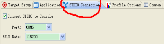
然后点击下面的run,开始运行,这时候可以看见LED等在亮了。
总结:本次实验是关于zedboard的第一个实验,在此做下简短的笔记,以供后面参考,其中有很多步奏省略了,参考一下网址,可以找到具体的操作。
1》https://blog.csdn.net/weixin_42639919/article/details/81130581
2》https://blog.csdn.net/hongbin_xu/article/details/74700556
对于PS和PL的联合开发,有待下一步。